Post by Deleted on Dec 4, 2016 10:58:55 GMT -7
LED basics link
I finished my Mach 5 with working lights several years ago. I wanted to enter it in an upcoming shows. However, I had several fears:
1. Will the 9 volt battery last the whole show?
2. Will the twin headlights generate enough heat to melt the headlight cover?
I would also like to:
1. Display the Mach 5 with the lights on and lights off.
2. Maybe add a little sizzle to the light show.
I though this kind of stuff was way out of my league, until I read an article by, and corresponded with Clyde Jones aka Zog. Clyde seems to know his way around electronics and electronic parts suppliers. Without his help, I probably would not have proceeded. I am in no way an expert on this stuff. I used Clyde's suggestions and did a little experimentation. These are my results. Use this info at your own risk.
Clyde suggested I needed a computer chip. Specifically a CD 4060. In geek speak the IC, CD 4060 is a 14-stage binary counter with Q1, Q2 Q3 and Q11 missing. The maximum division is 16,384 with Q14 going HIGH after 8,192 cycles and then LOW after another 8,192 cycles. It has internal components to create an oscillator. The CD 4060 is a CMOS chip. Minimum supply voltage 6v. Maximum supply voltage 15v. Max current per output 15mA. Maximum speed of operation 5MHz.
What does this mean to us model makers? If you are a modeler interested in making your creations come alive with blinking lights - marker lights, head or tail lights, strobes - this is a little chip that will do a lot of LED blinking for a very little money, power, or complexity.
The 4060 runs happily on 6 to 15 volts, and drives LEDs safely with only 12-15 mA (milli-amps) of current. Most LEDs thrive on 15 to 20 mA, so they are a bit dimmer then they might be otherwise, but they will not die from too much power and resistors are not needed. Your LEDs should last almost forever. Since the 4060 chip is a CMOS type, unlike some other chips, it uses very little power internally to run itself.
Another wonderful feature of the 4060 is they are cheap. $0.29 or less from some suppliers.
Clyde recommended and I successfully used:
Jameco Electronics
1355 Shoreway Road
Belmont, CA 94002
Phone: 1-800-831-4242 their web address is exactly what you think it should be.
The Jameco part number for this little beauty is #13151. They cost 29 cents for less than ten, 25 cents for 10-99 units.
You will need two other components to make the 4060 work. A capacitor and a resistor. Both are quite inexpensive also. The capacitor Clyde recommended was a CER, 0.01UF, 100V, 10%, AXIAL X7R. I have no idea what this means. Luckily Clyde told me they are part number #546257 and cost 10 cents each for 10-99 units.
The last part needed is a resistor - usually a 470,000 ohm or 470 Kilo-ohm resistor, 1/4W, 5%. I bought an assortment of 540 resistors for $12.95. Jameco # 103166.
The capacitor and the resistor set the basic frequency and 4060 chip divides it down.
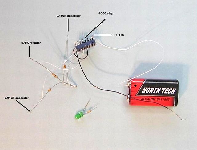
I bought a stick of 4060 chips, a pack of ten capacitors, an assortment of resistors, and two variable resistors (#182844 @ $0.75 each) as seen in the pix. Now let the fun, I hope, begin.


The 4060 chip is about 3/4" long and 5/16" wide. The chip is 1/8" tall but it is 9/32" tall including the wiring pins. See the next pix.

The second pix is a schematic of the 4060 with the pins numbered. This is the view from the top. The pins are pointing down. The notch is on the left.
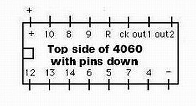
You will see the positive pin on the upper left. The negative pin is on the lower right. The forth pin from the left on the top row is the reset pin. It is also a negative pin.
All the numbered pins are both positive and negative pins. Each pin goes from "positive to negative" rather than from "on to off". If you connect a regular light bulb to these pins it will stay lit continuously because it doesn't matter which direction the current is flowing. However, if you connect a polarized LED between pins, the LED will light if and only if the pin connected to its positive lead is positive and the pin connected to its negative lead is in fact negative.
Take a look at the last pix. There is a green conventional bulb. It works with current from either direction. The blue LED will only work when positive current is coming from the left or pin 6. The red led is turned around so that it will only light when positive current is coming from the right or pin 4.

So as pins 4 and 6 alternate not from "on and off" but "positive and negative" all three bulbs will react differently.
If pin 6 is positive and the 4 pin is negative: the green bulb will be lit, the blue bulb will be lit, and the red bulb will be unlit.
When the current alternates, pin 6 becomes negative while pin 4 becomes positive. Now the green bulb is still lit, the blue bulb is unlit, and the red bulb is now lit.
So as the current at the pins alternate between positive and negative current, the omnidirectional conventional bulb is always lit, while the unidirectional LEDs blink on and off with the direction change of the current.
See, I told you it would be fun.
I finished my Mach 5 with working lights several years ago. I wanted to enter it in an upcoming shows. However, I had several fears:
1. Will the 9 volt battery last the whole show?
2. Will the twin headlights generate enough heat to melt the headlight cover?
I would also like to:
1. Display the Mach 5 with the lights on and lights off.
2. Maybe add a little sizzle to the light show.
I though this kind of stuff was way out of my league, until I read an article by, and corresponded with Clyde Jones aka Zog. Clyde seems to know his way around electronics and electronic parts suppliers. Without his help, I probably would not have proceeded. I am in no way an expert on this stuff. I used Clyde's suggestions and did a little experimentation. These are my results. Use this info at your own risk.
Clyde suggested I needed a computer chip. Specifically a CD 4060. In geek speak the IC, CD 4060 is a 14-stage binary counter with Q1, Q2 Q3 and Q11 missing. The maximum division is 16,384 with Q14 going HIGH after 8,192 cycles and then LOW after another 8,192 cycles. It has internal components to create an oscillator. The CD 4060 is a CMOS chip. Minimum supply voltage 6v. Maximum supply voltage 15v. Max current per output 15mA. Maximum speed of operation 5MHz.
What does this mean to us model makers? If you are a modeler interested in making your creations come alive with blinking lights - marker lights, head or tail lights, strobes - this is a little chip that will do a lot of LED blinking for a very little money, power, or complexity.
The 4060 runs happily on 6 to 15 volts, and drives LEDs safely with only 12-15 mA (milli-amps) of current. Most LEDs thrive on 15 to 20 mA, so they are a bit dimmer then they might be otherwise, but they will not die from too much power and resistors are not needed. Your LEDs should last almost forever. Since the 4060 chip is a CMOS type, unlike some other chips, it uses very little power internally to run itself.
Another wonderful feature of the 4060 is they are cheap. $0.29 or less from some suppliers.
Clyde recommended and I successfully used:
Jameco Electronics
1355 Shoreway Road
Belmont, CA 94002
Phone: 1-800-831-4242 their web address is exactly what you think it should be.
The Jameco part number for this little beauty is #13151. They cost 29 cents for less than ten, 25 cents for 10-99 units.
You will need two other components to make the 4060 work. A capacitor and a resistor. Both are quite inexpensive also. The capacitor Clyde recommended was a CER, 0.01UF, 100V, 10%, AXIAL X7R. I have no idea what this means. Luckily Clyde told me they are part number #546257 and cost 10 cents each for 10-99 units.
The last part needed is a resistor - usually a 470,000 ohm or 470 Kilo-ohm resistor, 1/4W, 5%. I bought an assortment of 540 resistors for $12.95. Jameco # 103166.
The capacitor and the resistor set the basic frequency and 4060 chip divides it down.
I bought a stick of 4060 chips, a pack of ten capacitors, an assortment of resistors, and two variable resistors (#182844 @ $0.75 each) as seen in the pix. Now let the fun, I hope, begin.


The 4060 chip is about 3/4" long and 5/16" wide. The chip is 1/8" tall but it is 9/32" tall including the wiring pins. See the next pix.

The second pix is a schematic of the 4060 with the pins numbered. This is the view from the top. The pins are pointing down. The notch is on the left.

You will see the positive pin on the upper left. The negative pin is on the lower right. The forth pin from the left on the top row is the reset pin. It is also a negative pin.
All the numbered pins are both positive and negative pins. Each pin goes from "positive to negative" rather than from "on to off". If you connect a regular light bulb to these pins it will stay lit continuously because it doesn't matter which direction the current is flowing. However, if you connect a polarized LED between pins, the LED will light if and only if the pin connected to its positive lead is positive and the pin connected to its negative lead is in fact negative.
Take a look at the last pix. There is a green conventional bulb. It works with current from either direction. The blue LED will only work when positive current is coming from the left or pin 6. The red led is turned around so that it will only light when positive current is coming from the right or pin 4.

So as pins 4 and 6 alternate not from "on and off" but "positive and negative" all three bulbs will react differently.
If pin 6 is positive and the 4 pin is negative: the green bulb will be lit, the blue bulb will be lit, and the red bulb will be unlit.
When the current alternates, pin 6 becomes negative while pin 4 becomes positive. Now the green bulb is still lit, the blue bulb is unlit, and the red bulb is now lit.
So as the current at the pins alternate between positive and negative current, the omnidirectional conventional bulb is always lit, while the unidirectional LEDs blink on and off with the direction change of the current.
See, I told you it would be fun.
